
I’ve found, while working with customers, that one very useful component of profile views has been underutilized since its addition in AutoCAD Civil 3D 2010. This component I’m referring to is the profile view hatch. The initial perception users have of this component is that it is only used to show cut and fill locations between an existing surface and a proposed surface. But, that’s not the only use. When creating multiple proposed surfaces that are based on material (ie. Paving), this component adds an additional dimension to profile views. Reviewers and contractors can now see an added entity that helps in deciphering the vertical scale and location of underground utilities. In this post I’ll share with you an easy way to use this graphic which will add more meaning to your profile views.
See the rest of this post…
In this post I’ll be using AutoCAD Civil 3D 2011. However, the same process can be applied with 2010 and 2012.
The following steps will assume you already have an existing surface (EG) and a proposed surface (PG). For simplifying this post, I will show you a way to show the contiguous paving section depth on all your profile views in your project. You can expand upon this concept and create even more surfaces that show more detail of materials that make up your entire paving section.
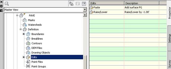
- Create a new surface and call it PAVE.
- Paste in your PG surface into PAVE.
- Lower your PAVE surface by the thickness of the paving section. In this example I lowered it by –1.0’
- Create a boundary or boundaries to only include the paving areas. Use your proposed paving layers to create closed polylines defining your areas. (You may choose to have additional boundary layers that can be frozen for this purpose.)

- Create surface profiles for all your alignments.

- For each profile view, go to the profile view properties hatch tab and create a new Cut Area. You’ll want to create a hatch style that depicts the paving the way you and your company desire. This style is part of the General Multipurpose Shape Styles. (You may have a company standard paving style already created if you show assemblies in plotted section views.)

Some things to keep in mind…
- This doesn’t have to be done only at the end of the design. If established early on, this is very helpful for designing your utilities with a visual aspect to check possible cover issues.
- PAVE surface will update as you modify your proposed grading (PG) since it is pasted into it.
- If pavement areas change, just adjust your boundary polylines.
- You can establish surfaces for all separate material layers to show more detailed paving sections. Use the same process starting with the PG pasted in.
Cheers!
Jonathan Stewart
CADvisers


I forgot to mention that this has a dual purpose…
These material surfaces are a quick and accurate way to allow you to do your material volume takeoffs for your entire site. It doesn’t limit you to only locations that you’re using corridors.