
I’ve fielded several support calls recently about images in AutoCAD. They all revolved around AutoCAD’s performance, or lack thereof, in the matter. Read on to find out how to remedy many of these problems.
Some of the problems were that the images weren’t printing well. Some had trouble loading a 650MB file (how could they not?).
Coming from a photographic background, I have some insight into the reality of image size and type. The fact of the matter is a 650MB image is so much overkill it’s not funny. Using an image of that size on a 24×36 plot is like using a 349E (http://www.cat.com/cda/layout?m=423401&x=7) to fill your kid’s sandbox.
First, let’s talk about image type. Often firms will receive a large TIF of an orthophoto. Given the same resolution, JPG or PNG file are far smaller in size than TIF’s. True, TIF’s are “technically” better quality, but the compression algorithms for JPG and PNG so good that generally only a trained eye can tell the difference…and that’s at a very high degree of magnification. And that’s just zoomed in super-tight on your monitor. You know what? When you print it, there will be no discernable difference. Here’s a thread about TIF vs JPG http://www.velocityreviews.com/forums/t250020-tiff-vs-jpg.html
Second, let’s talk about resolution. Resolution is the single most important attribute of your image that can cause problems in AutoCAD, MS Word, any application that can display and print them. the fact is, you probably have way more than you need.
In the photographic world, it is accepted that the human eye can discern no more than about 300 pixels per inch when printed on paper. What does this mean? Here’s a Wikipedia post about it (yeah I know it’s Wiki, but this pretty much rings true here) http://en.wikipedia.org/wiki/Pixel_density.
The other thing is your printer; it may only be able to resolve 150 pixels per inch, depending on the model. For an engineering drawing, I would rarely bother to go with anything higher than 150 pixels per inch, but feel free to go a little higher.
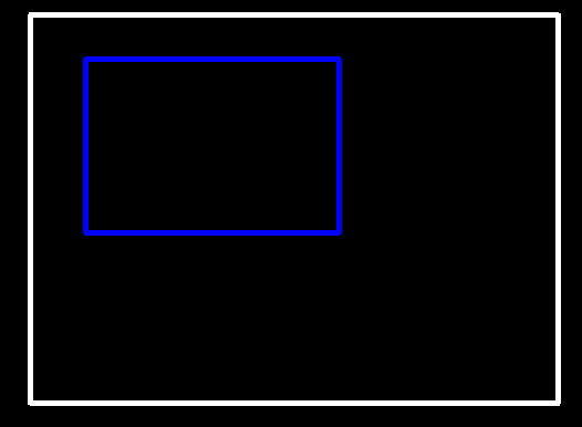
You need to do a little math. Forget about the paper size, think about how big the image is on the paper. The image below show a white paper outline and a blue image outline. If the paper in this case is 24×36, the image may be 14×21. So if you need 150 pixels per in, your image’s resolution at 14×21 would be 2100×3150. The saved JPG file should be no more than a couple of megabytes. Super easy for AutoCAD to deal with.
The last thing that may throw a wrench into the mix is georeferencing the image. Your TIF orthophoto probably came with a world file TFW. This is what places the image in your coordinate system. If you have Autodesk Raster Design, this is no problem. You can resize the image with it and create the new JPG and JGW world file at the same time. If you don’t have RD, you could attach the TIF, then attach the JPG and overlay it, then remove the TIF.
Hopefully I’ve saved you some trials and tribulations with imaging in AutoCAD.
Matt


What about .sid images? These things are fairly large, upwards of 300 megs. Is there any info out there that can help with performance issues due to the usage of .sid images. Thanks
SID images a a little different beast. Their resolution varies depending on how far you’re zoomed in, at least in the viewer. For a given image size, SID’s run far faster typically. I’m a little uncertain how they run inside AutoCAD however. I’m fairly certain you can still resize the image in SID as well if you’re having performance issues. I’m just not sure if the world file can be retained. I dont’ think Raster Design can resize SID’s, but I could be wrong.
I use *.sid files all the time that are upwards of 1 GB or more. I usually downsize them using a free program by Lizard Tech called GeoViewer 5 http://www.lizardtech.com/downloads/index.php?section=geotrial#geotrial
it will allow you to write out a manageable image and world file for you.
I use the same program as Jason. It really works well to crop out only the area you need for your site as well as creating a new world file so it remains georeferenced. This makes the image in Civil 3D much easier to manage and when zooming extents you don’t have to worry about zooming back into your specific site location.
People with good eyesight, in good conditions, and when viewing from close range, can detect the dots at 300dpi. Depending on the printer and the intended use you may want to bump up the resolution to 600dpi.
In the laser printer world I find it fairly easy to distinguish 600dpi vs. 300dpi print jobs. And I can get a noticeable improvement in grey shades using the HP FastRes 1200 option.
Dots per inch (DPI) can be different than Pixels per inch (PPI). Often printer manufacturers speak of 600 or 1200DPI resolution. Remember, they have to place 3 dots in one place on an RGB machine to get a single colour at that particular Pixel. Thus 600DPI may actually be 150PPI. The resolution of the image should not need to be bumped to 600ppi, only the printer resolution.