
I was recently given the task of drawing up some concept layout plans for a high school. With an emphasis on concept, we don’t have an architect on board yet. I am definitely not qualified to start drawing up building plans so I did the next best thing. I found a few other local high schools with a similar student count and found them on Google Earth. A “few” clicks later I had linework for a concept high school building. How did I do it? Find out below the cut.
- Open up Google Earth and zoom to the building that you want to use.

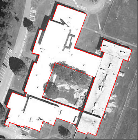
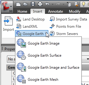
- Open up your Civil 3D drawing and on the Insert tab click drop down for “Google Earth” in the Import section. I picked “Google Earth Image” since I only needed the graphic and not the surrounding surface. This will bring a black and white scaled image from where you are zoomed in Google Earth into your Civil 3D drawing. (It doesn’t matter where the image is located in the drawing since we are just using this image as a template to trace.)

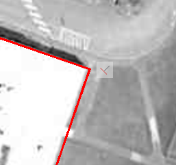
- Sadly there is no magic button to click that will automatically trace the building. Also sadly, with aerial photographs things which should be all nice ninety degree angles aren’t always. This is where geometric constraints come in. Using a polyline (closed at the end) I am going to roughly trace around the building making sure at least the first segment is close to the alignment that I want. (Here I started in the upper left corner and went counterclockwise. I chose to include some overhangs and ignore others, remember my task here was to get a pretty concept outline that is surely going to change once an architect gets on board. I just wanted a placeholder in my parking lots and driveways.)
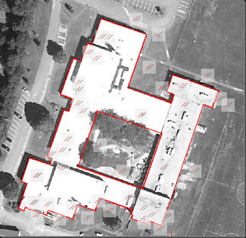
- Next I used the geometric constraint commands. (Type GC into your command line and tab through all the different GC commands. There are lots to pick from!) For my building I first used GCPERPENDICULAR (which is too long to type so I really only typed GCPERP and hit the tab key for it to fill in the rest and then hit enter. I am all about saving keystrokes!) on my first and second segments. Remember that the first segment you pick will be the one that doesn’t change and the second will be the one that does change. A small icon (that will not print) will show that there is now a constraint on that corner.

- Next I am going to use GCPARALLEL (GCPA tab enter) and reference one of these segments with each of the other segments around the building. This will make everything a happy 90 degrees with one another. (I actually originally did GCPERP around the whole building but my computer didn’t like all the thinking once I got to the next step of shifting things to realign to the image. Sort of the scenario of when you cut a piece of wood you should use the original as a template otherwise if you use the piece you just cut and then the piece you just cut and then the piece you just cut, you will end up with slowly changing piece of wood.) For the central courtyard, in addition to the GCPARALLEL, I used two GCCOLINEAR commands to keep them in line with other walls so that when I move and rotate the building for my concept later, I don’t inadvertently leave the courtyard behind. (I did take the screen shot before I implemented the GCCOLINEAR commands though so that is why you don’t see the constraint icons.)

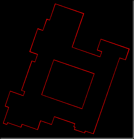
- While the linework could be good enough for what I want at this point, since everything is nice and square and pretty looking, I did want it a little closer to the original as far as size goes since I was trying to match the square footage of the template school building. You will notice that when things snapped parallel it shifted some lines away from where they originally were located. Now that everything is constrained, it is easy to just drag a single node at a time and all of the constraints that you defined will stay keeping the building nice and square.
- At this point you can either delete the image or just turn it off from view and go about using the building footprint however you want. You can also right click on one of the constraints and select “Hide All” if they become distracting.


While geometric constraints aren’t anything special to Civil 3D, the wheels in my brain are turning with other uses. Parking lot layouts. Retaining wall cross section details. What sort of uses can you think of?


I solve this problem another way, using Polar Angle Measurement.
Basically, it looks at the polar angle relative to the last line segment. Try it out:
* Turn Polar Tracking on (Shift-Rightclick, Osnap Settings, Polar Tab)
* Set your increment angle to the smallest angle you’ll be tracing that is “standard” (22.5, 45, 90)
* Set Polar Angle Measurement to “Relative to last segment”
Now, draw a line anywhere at any angle, then your next segment at approx 90-degrees. You’ll notice your polar angle snap will guide you from there. Very handy! And, beyond the method described in this post, you can set it to angles less than 90 degrees.
Neat tip Andrew! Thanks for sharing. I’ve never used the polar tracking but will definitely give it a go.
WHEN I IMPORTED THE GOGGLE IMAGE ALL I GOT WAS THE IMAGE FRAME. I’M USING CIVIL3D 2009, WOULD THAT BE A PROBLEM?
ANY IDEAS WOULD BE GREAT.
Hi Robert. I haven’t had the issue you describe but a quick Google search shows other people had the same issue when Google Earth was minimized. Zoom to where you want in Google Earth and keeping the program maximized just switch to Civil 3D. Let us know if that works!
THANKS KATI, THAT WORKED GREAT.
Correct. When importing from google earth, you cannot minimize the google earth window during the import. As stated, simply switch back to civil 3D. another thing we found necessary is in the surface commands in the toolspace you must edit the Import GES Surface and click on the google earth options. Change google earth rows and google earth column to 70 for each.
This is a great write up…thank you