
With things being the way they are and many companies experiencing financial troubles, some people may not be getting an end of the year bonus this year. I’m not going to be handing out a nice fat bonus check to all the wonderful civil3d.com readers but I do have a little end of the year bonus for you that will save you time and in my unbiased opinion will change the way you design behind the curb. It’s a nice “simple” shoulder subassembly but it solves two problems that I have always grumbled about. Problem #1 is I wanted a subassembly in fill to daylight with an upward slope if the slope it was connecting to was sloping upward and with a downward slope if the slope it was connecting to was sloping downward. This problem is solved with this subassembly. Problem #2 is I wanted the same subassembly to truncate the shoulder if the shoulder intersects with the surface. This is often the case when I am doing a road rehab job and don’t need a full shoulder and have less area of disturbance. This problem is also solved with this subassembly.
So this wonderful end of the year bonus comes with a little caveat, it’s sort of like a Lego® set, I’m going to give you all of the pieces but you have to put it together yourself in order to use it. Although I can’t stop you from putting it all together and handing it out like candy, I do encourage you to hand others the tutorial and let them put it together themselves. This is two bonuses in one, not only will it walk you through the thought process and set up of the Autodesk Subassembly Composer but I think it will be a subassembly that you will use again and again. So without further ado… Your End of the Year Bonus is below the cut!
-
 OPEN: Open a new file in the Autodesk Subassembly Composer. Save it as SmartShoulderDaylight.pkt [Or whatever other file name you deem appropriate.]
- DEFINE INPUT PARAMETERS: Select the “Input Parameters” tab. Click “Create input parameter” to create 5 input parameter variables. Rename them as follows [ex. Variable (Type, Default Value). Feel free to change the default values to the most common values used in your area.]:
- ShoulderWidth (Double, 5)
- ShoulderSlope (Double, 0.03) [This subassembly assumes that the shoulder slope is always directed to drain towards the road.]
- DaylightSlope (Double, 0.5) [This subassembly assumes the same daylight slope is used for cut and fill but with a few modifications you could add a second daylight slope variable.]
- TruncateShoulder (Boolean, True)
- ExtendShoulder (Boolean, True)
- DEFINE TARGET PARAMETERS: Select the “Target Parameters” tab. Click the “Create target parameter” to create 1 target parameter variable. Rename it as follows:
- TargetSurface (Surface, 3) [Note that you are going to want to change this variable once this is fully built to see how your subassembly reacts.]
- DEFINE THE PACKET SETTINGS: Select the “Packet Settings” tab. Define as follows:
- Subassembly Name: SmartShoulderDaylight
- Help file: [Leave this blank for now but we will be talking about help files in Part 6 and this is where you would add it.]
 Image file: [You can insert any image here, I’ve created a sample one located to the right, feel free to right click and save it to your computer. For consistency sake I would name it SmartShoulderDaylight.png. Then reference the file location to where you save it.]
- Side parameter: Right [We are going to define the right side but like all subassemblies, when you bring this into Civil 3D you can switch it from the default right to the left when you want to apply it to the left side of an assembly.]
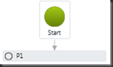
- DEFINE THE APPLICATION POINT (P1): Drag a point from the Tool Box pane to the Flowchart pane and place it under the “Start”. Connect Start to the point just placed. Define point just placed as follows:
 Code names:
- DisplayName: P1
- Name: P1
- Point Geometry Type: OffsetAndDeltaElevation
- From Point: Origin
- Offset: 0
- Delta Elevation: 0
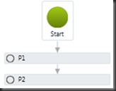
- DEFINE THE DEFAULT SHOULDER POINT (P2): Drag a point from the Tool Box pane to the Flowchart pane and place it under point P1. Connect point P1 to the point just placed. Define point just placed as follows:
 Code names:
- DisplayName: P2
- Name: P2
- Point Geometry Type: SlopeAndOffset
- From Point: P1
- Offset: ShoulderWidth
- Delta Elevation: ShoulderSlope
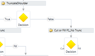
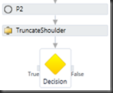 DEFINE TRUNCATESHOULDER CONDITIONAL: Drag a “General Condition” conditional and a decision under point P2. Connect point P2 to the conditional just placed and connect the conditional just placed to the decision just placed. Define the conditional just placed as follows:
- Condition Expression: TruncateShoulder
- Display Name: TruncateShoulder
- ANALYZE P1 IN CUT/FILL WHEN TRUNCATESHOULDER=TRUE:
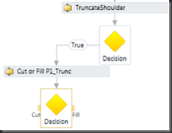 Drag a “Cut or Fill” conditional and a decision to the left of the TruncateShoulder decision. Connect the the True (left) side of the “TruncateShoulder” decision to the conditional just placed and connect the conditional just placed to the decision just placed. Define the conditional just placed as follows:
- Condition Point: P1
- Condition Surface: TargetSurface
- Display Name: Cut or Fill P1_Trunc
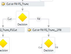
- ANALYZE P2 IN CUT/FILL WHEN TRUNCATESHOULDER=TRUE and P1=CUT:
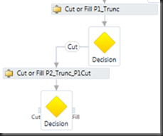 Drag a “Cut or Fill” conditional and decision to the Cut (left) side of the “Cut or Fill P1_Trunc” decision. Connect the Cut (left) side of the “Cut or Fill P1_Trunc” decision to the conditional just placed and connect the conditional just placed to the decision just placed. Define the conditional just placed as follows:
- Condition Point: P2
- Condition Surface: TargetSurface
- DisplayName: Cut or Fill P2_Trunc_P1Cut
- ANALYZE P2 IN CUT/FILL WHEN TRUNCATESHOULDER=TRUE and P1=FILL: Drag a “Cut or Fill” conditional and decision to t
 he Fill (right) side of the “Cut or Fill P1_Trunc” decision. Connect the Fill (right) side of the “Cut or Fill P1_Trunc” decision to the conditional just placed and connect the conditional just placed to the decision just placed. Define the conditional just placed as follows:
- Condition Point: P2
- Condition Surface: TargetSurface
- Display Name: Cut or Fill P2_Trunc_P1Fill
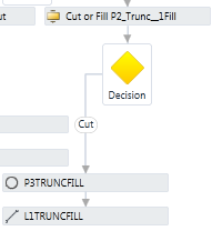
- TRUNCATE SHOULDER IF P1=CUT and P2=FILL and TRUNCATESHOULDER=TRUE (P3TRUNCFILL and L1TRUNCFILL): Drag a point and a link to the right of the “Cut or Fill P2_Trunc_P1Cut” decision. Connect the Fill (right) side of the “Cut or Fill P2_Trunc_P1Cut” decision to the point just placed and connect the point just placed to the link just placed.
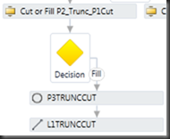 Define point just placed as follows:
- Code names: Daylight, Daylight_Cut
- DisplayName: P3TRUNCCUT
- Name: P3
- Point Geometry Type: SlopeToSurface
- From Point: P1
- Slope: ShoulderSlope
- Offset to use in Preview: 2
- Surface Target: TargetSurface
- Define link just placed as follows:
- Code names: Top, Datum, Top_Cut, Datum_Cut
- DisplayName: L1TRUNCCUT
- Name: L1
- Start point: P1
- End point: P3
- TRUNCATE SHOULDER IF P1=FILL and P2=CUT and TRUNCATESHOULDER=TRUE (P3TRUNCFILL and L1TRUNCFILL): [This is exactly the same as the point and link used for P1=CUT and P2=FILL except the code names are different. If you didn’t care about the code names you could use the same point and link and connect them accordingly.] Drag a point (P3) and a link (L1) to the left of the “Cut or Fill P2_Trunc_P1Fill” decision. Connect the Cut (left) side of the “Cut or Fill P2_Trunc_P1Fill” decision to the point just placed and connect the point just placed to the link just placed.
 Define point just placed as follows:
- Code names: Daylight, Daylight_Fill
- DisplayName: P3TRUNCFILL
- Name: P3
- Point Geometry Type: SlopeToSurface
- From Point: P1
- Slope: ShoulderSlope
- Offset to use in Preview: 2
- Surface Target: TargetSurface
- Define link just placed as follows:
- Code names: Top, Datum, Top_Fill, Datum_Fill
- DisplayName: L1TRUNCFILL
- Name: L1
- Start point: P1
- End point: P3
- ANALYZE P1 IN CUT/FILL WHEN TRUNCATESHOULDER=FALSE: Drag a “Cut or Fill” conditional and a decision to the right side of the “TruncateShou
 lder” decision. Connect the False (right) side of the “TruncateShoulder” decision to the conditional just placed and connect the conditional just placed to the decision just placed.Define the conditional just placed as follows:
- Condition Point: P1
- Condition Surface: TargetSurface
- Display Name: Cut or Fill P1_No Trunc
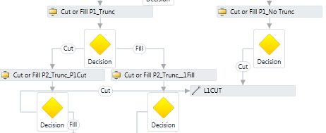
- CREATE DEFAULT SHOULDER LINK FOR CUT (L1CUT): [This will be used when TruncateShoulder=True but P1 and P2 both equal cut (meaning that the surface does not intersect with the
 shoulder).] Drag a link to the left side of the “Cut or Fill P1_No Trunc” decision. Connect the “Cut or Fill P1_No Trunc” Cut (left) decision to the link just placed. Also connect the “Cut or Fill P2_Trunc_P1 Cut” Cut (left) decision to the same link. Define the link just placed as follows:
- Code names: Top, Datum, Top_Cut, Datum_Cut
- DisplayName: L1CUT
- DisplayName: L1
- Start point: P1
- End point: P2
- CREATE DEFAULT SHOULDER LINK FOR FILL (L1FILL): [This will be used when TruncateShoulder=True but P1 and P2 both equal fill (meaning that the surface does not intersect with the shoulder).] Drag a link
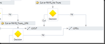 to the right side of the “Cut or Fill P1_No Trunc” decision. Connect the “Cut or Fill P1_No Trunc” Fill (right) decision to the link just placed. Also connect the “Cut or Fill P2_Trunc_P1 Fill” Fill (Right) decision to the same link. Define the link just placed as follows:
- Code names: Top, Datum, Top_Fill, Datum_Fill
- DisplayName: L1FILL
- DisplayName: L1
- Start point: P1
- End point: P2
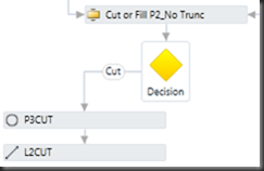
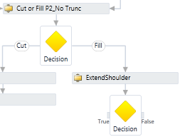
- ANALYZE P2 IN CUT/FILL WHEN NOT TRUNCATING SHOULDER: Drag a “Cut or Fill” conditional and decision under L1CUT and L1FILL.
 Connect the link L1CUT to the conditional just placed and connect the conditional just placed to the decision just placed. Also connect the link L1FILL to the same conditional. Define the conditional just placed as follows:
- Condition Point: P2
- Condition Surface: TargetSurface
- Display Name: Cut or Fill P2_No Trunc
- DAYLIGHT AT SLOPE IF P2=CUT and NOT TRUNCATING SHOULDER (P3CUT and L2CUT): [Note that all of the daylighting points will be P3 and all of the shoulder slopes are L1 and all of the daylight slopes are L2, but they are all named with defining characteristics for display purposes in the flowchart.] Drag a point and a link to the left of the “Cut or Fill P2_No Trunc” decision. Connect the Cut (left) side of the “Cut or Fill P2_No Trunc” decision to the point just placed and connect the point just placed to the link just placed.
 Define point just placed as follows:
- Code names: Daylight, Daylight_Cut
- DisplayName: P3CUT
- Name: P3
- Point Geometry Type: SlopeToSurface
- From Point: P2
- Slope: DaylightSlope
- Offset to use in Preview: 6
- Surface Target: TargetSurface
- Define link just placed as follows:
- Code names: Top, Datum, Top_Cut, Datum_Cut
- DisplayName: L2CUT
- Name: L2
- Start point: P2
- End point: P3
- DEFINE EXTENDSHOULDER CONDITIONAL: [Note that the
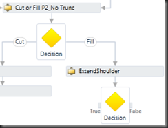 extend shoulder case is only pertinent when P2 is in fill.] Drag a “General Condition” conditional and a decision to the right of the “Cut or Fill P2_No Trunc” decision. Connect the Fill (right) side of the “Cut or Fill P2_No Trunc” decision to the conditional just placed and connect the conditional just placed to the decision just placed. Define the conditional just placed as follows:
- Condition Expression: ExtendShoulder
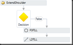
- Display Name: ExtendShoulder
- DAYLIGHT AT SLOPE IF P2=FILL and EXTENDSHOULDER=FALSE (P3FILL and L2FILL): Drag a point and a link to the right of the “ExtendShoulder” decision. Connect the False (right) side of the “ExtendShoulder” decision to the point just placed and connect the point just placed to the link just placed.
 Define point just placed as follows:
- Code names: Daylight, Daylight_Fill
- DisplayName: P3FILL
- Name: P3
- Point Geometry Type: SlopeToSurface
- From Point: P2
- Slope: -DaylightSlope
- Offset to use in Preview: 6
- Surface Target: TargetSurface
- Define link just placed as follows:
- Code names: Top, Datum, Top_Fill, Datum_Fill
- DisplayName: L2FILL
- Name: L2
- Start point: P2
- End point: P3
- DAYLIGHT AT SLOPE IF P2=FILL and EXTENDSHOULDER=TRUE (P30TESTSLOPE and P40TESTSLOPE): [These are temporary analysis points which is why I am numbering them with an extra 0 on the end to differentiate them from the actual points which are used by the subassembly. Since this version of the SAC only has a horizontal target surface, try changing the value of the delta elevation of the P40TESTSLOPE to –0.2 or 0.2 when the TargetSurface preview value is set to –3 and ExtendShoulder is set to True when the subassembly is complete.] Drag two points to the left side of the “ExtendShoulder” decision. Connect the True (left) side of the “ExtendShoulder” decision to the first point just placed and connect the first point just placed to the second point just placed.
 Define first point just placed as follows:
- Code names:
- DisplayName: P30TESTSLOPE
- Name: P30
- Point Geometry Type: SlopeToSurface
- From Point: P2
- Slope: -DaylightSlope
- Offset to use in Preview: 6
- Surface Target: TargetSurface
- Define second point just placed as follows:
- Code names:
- DisplayName: P40TESTSLOPE
- Name: P40
- Point Geometry Type: OffsetAndDeltaElevation
- From Point: P30
- Offset: 0.2
- DeltaElevation: 0
- ANALYZE P40TESTSLOPE IN CUT/FILL WHEN EXTENDSHOULDER=TRUE: Drag a “Cut or Fill” conditional and a decision under point P40TESTSLOPE. Connect the False (right) side of the “TruncateShoulder” decision to the conditional just placed and connect the conditional just placed to the decision just placed.
 Define the conditional just placed as follows:
- Condition Point: P40
- Condition Surface: TargetSurface
- Display Name: Cut or Fill P40 Slope
- Define the decision just placed as follows:
- FalseLabel: Fill/Downward
- TrueLabel: Cut/Upward
- EXTEND SHOULDER IF P40=CUT and EXTENDSHOULDER=TRUE (P3EXTFILL and L2EXTFILL): [P30 connects to the surface as if the daylight slope is used. P40 is placed slightly to the right of P30. If P40 is in cut than that means that the target surface slopes up from the connection point, therefore in order to not create a “false swale” by sloping down the target surface and then the existing grade sloping up, we are going to extend the shoulder slope out to the target surface.] Drag a point and a link to the left of the “Cut or Fill P40 Slope” decision. Connect the Cut/Upward (left) side of the “Cut or Fill P40 Slope” decision to the point just placed and connect the point just placed to the link just placed.
 Define point just placed as follows:
- Code names: Daylight, Daylight_Fill
- DisplayName: P3EXTFILL
- Name: P3
- Point Geometry Type: SlopeToSurface
- From Point: P2
- Slope: ShoulderSlope
- Offset to use in Preview: 6
- Surface Target: TargetSurface
- Define link just placed as follows:
- Code names: Top, Datum, Top_Fill, Datum_Fill
- DisplayName: L2EXTFILL
- Name: L2
- Start point: P2
- End point: P3
- DAYLIGHT AT SLOPE IF P40=FALSE and EXTENDSHOULDER=TRUE:
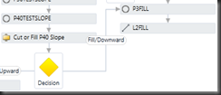 [If P40 is in fill than that means that the target surface slopes down from the connection point and the subassembly behave as it would normally by sloping down to the surface.] Connect the Fill/Downward (right) side of the “Cut or Fill P40 Slope” decision to the point P3FILL.
- BRING INTO CIVIL 3D: Open Autodesk Civil 3D 2010 or 2011.
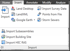 On the Insert ribbon click on the word “Import” to extend the ribbon to show some of the less commonly used commands. Then click the one that says “Import Subassemblies”. Browse to the location where you saved your subassembly under where it says “Source File”. [I’ve made my own tool palette with all of the subassemblies that I have been creating. You may chose to do the same.] Once it is brought in to your Tool Palette you can use it just like you do any other subassembly pieces.


So that’s it. Twenty-four simple steps. Go ahead and build it and try it and let me know what you think. I would love to hear about your successes and failures so be sure to come back and comment here!


You sir are the man! I wasn’t so excited to try this thing out yet -but now… I Can’t Wait!
oops -sorry Kati. You miss are the WOman!
Thank you for the compliment MKling. I look forward to hearing what your opinion is once you try it out! Be sure to come back and tell us. 🙂
Nice work on the Subassembly Composer series 🙂