
When is a point, not a point?
This is something I get asked about and I finally did something about it last week to add this to our templates.
That is, rather, how do you label a coordinate without creating a point object? If we create a point, we need to think about the number and the description of that point.
Here are two suggestions:
Option 1: Use an AutoCAD FIELD.
The AutoCAD field has a nice way to get to some AutoCAD properties. For example, I use a FIELD to organize and label each Assembly that I use in my drawing. By using a FIELD, I can add a label for the coordinate of the start or end of a line. 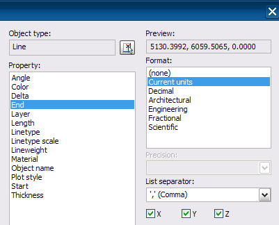
With some re-arranging and the copy and pasting of the FIELD, I can actually get a N:6059.5065, E: 5130.3992 label.
If one moves the end of the line, the coordinates will update.
Yeah! Too bad it is not one step.
Option 2: Use a Civil 3d Line Label Style (or Curve)
Civil 3d Line and Curve Labels seems to be a catch-all for labeling. With these labels, we can create Segment Grade Labels, Distance Labels, Bearing and Distances, as well as Curve Labels.
With 2009, we can use these General Line and Curve labels in my parcels too!
From Settings Tab, General Collection, Label Styles and either the Lines or Curves, create a new Label style called: Line Northing Easting [Start] label that contains the following text:
N:<[General Segment Start Y(Uft|P3|RN|AP|Sn|OF)]>
E:<[General Segment Start X(Uft|P3|RN|AP|Sn|OF)]>

I can now label one or two simple locations with a Northing and Easting and not have to worry about a description of the point or the point number.
The label snaps to the correct end too, or should I say the “correct Start.”


Option 1.1: Use an AutoCAD FIELD. Part 2.
– Create an MText object.
– Edit Text, Select your MText, right click, ‘Insert Field…’
– Under ‘Field names:’ select ‘Object’
– Under ‘Object Type’: pick the ‘Select Object’ button.
– At the prompt ‘Select object:’ type ‘L’ or ‘Last’
– Under ‘Property:’ select ‘Position’
– Then you have the option of inserting ‘X’ and/or ‘Y’ and/or ‘Z’
– You can create one field for ‘X’, one for ‘Y’ and another for ‘Z’, and add a different prefix and/or suffix under ‘Additional Format…’ for each of them.
Update for “Option 1.1: Use an AutoCAD FIELD. Part 2.” I forgot to mention, just in case someone didn’t notice. With this approach there’s no need to draw a line. This MText shows its own position coordinates at the insertion point. Plus it can be copied and each copy retains its own information.
Another option is to creat an alignment station offset label that consists only of a northing and easting. So long as you have an alignment in your drawing you can label the coordinates of any point.