
I am hoping to get a series of subassembly posts going that will assist you in learning to read and troubleshoot your corridors. Chapters 10, 11, and 12 in Mastering AutoCAD Civil 3D 2008 include a lot of information about how assemblies and corridors are constructed. We’ll explore some more topics over the next few months.
So you choose a daylight subassembly and you wanted your daylight link to be a maximum of 10′ long like this….

But instead it does something crazy like this…

What went wrong? Read more to find out.
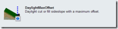
There are two subassemblies that seem like they would be the same. DaylightMaxWidth and DaylightMaxOffset. They look very similar and seem to ask for the same information. A lot of people mix up these two subassemblies and wind up frustrated.
DAYLIGHTMAXWIDTH

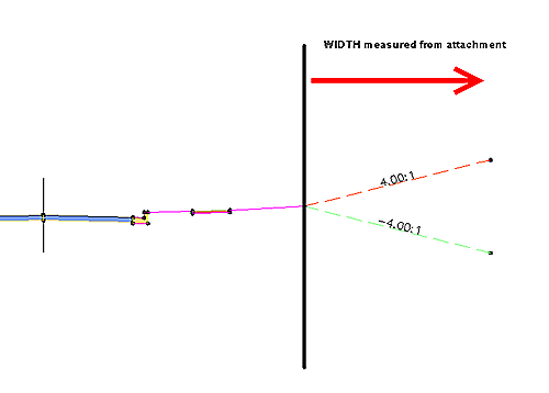
When placing this subassembly, you are prompted for a maximum width.

This width is measured from the point of attachment. In the figure below, I am showing it attached to my exterior sidewalk buffer. The width of 10′ will be measured starting from that buffer.
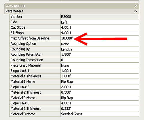
DAYLIGHTMAXOFFSET
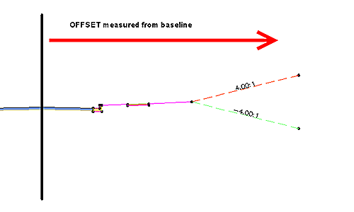
When placing this subassembly, you are prompted for maximum offset- this means offset from baseline.
The offset is measured from the assembly baseline. So an offset of 10′ would actually wind up going BACKWARDS from the point of attachment. This would make my corridor look strange. However, even if you do it “wrong” your assembly will look fine, as seen in the below image.
So- the lesson to be learned here is that while both subassemblies have their place, most people intend to choose the maxwidth (or minwidth) subassemblies when they are first building corridors.

